How to use Unigraphics NX4 Motion Simulation in Timing Diagram Design Process - Part 3
In [How to use Unigraphics NX4 Motion Simulation in Timing Diagram Design Process - Part 2], we've finished setting the driver of revolute joint of the indexing mill. Then let's set the joint for the punch die.

Movement of the punch die is different from the indexing mill. It moves only in linear motion along Z axis (normal to top face of indexing mill). The joint for this kind of movement is called "Slider" joint. Here is how to set it:
1. Select Joint command.
2. Select "Slider" joint icon in the joint dialog box.
3. Select first link icon.
4. Select link "Die" as we previously created

5. Click at the "Orientation on the first link" icon.
6. Select "Point" from the drop-down menu.
7. Select center point of the cylinder as shown above to define the location of the slider joint.

8. Select "Vector" from the drop-down menu to define the direction of the slider joint.
9. Select the bottom face of cylinder to define the vector perpendicular to that plane. See the Z axis pointing downward.
10. Rename the slider joint to "J_Die".
11. Click Ok to confirm.
The slider joint setting procedures are almost done. Still to set the driver of this joint.

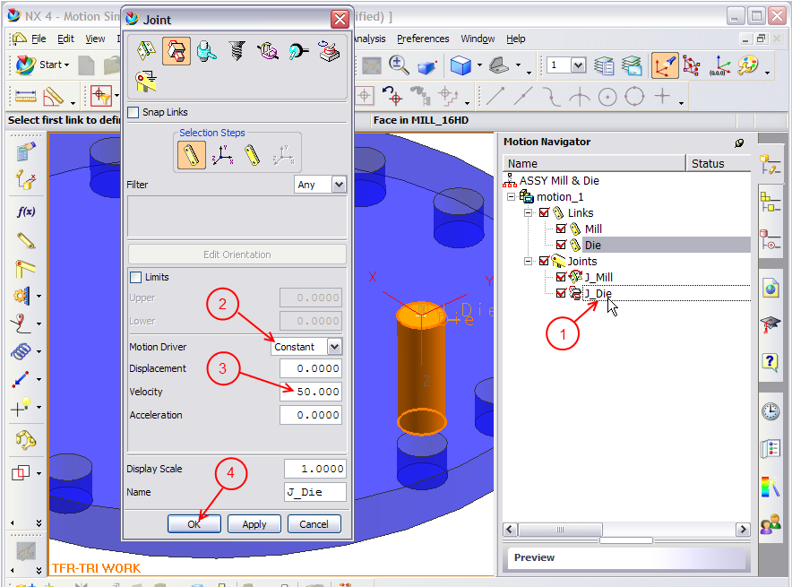
1. Right-click at the slider joint J_Die and select Edit to open the dialog box.
2. Change the slider joint motion driver to "Constant".
3. Type any value in the velocity text box e.g. 50. This sets the velocity of this slider joint to 50 mm/s.
4. Click Ok to confirm.
We've finished the setting procedures for motion simulation and we can now start simulation. But please note that the movement of indexing mill and punch are still not the same as what we need.

To see the motion simulation, follows the steps below:
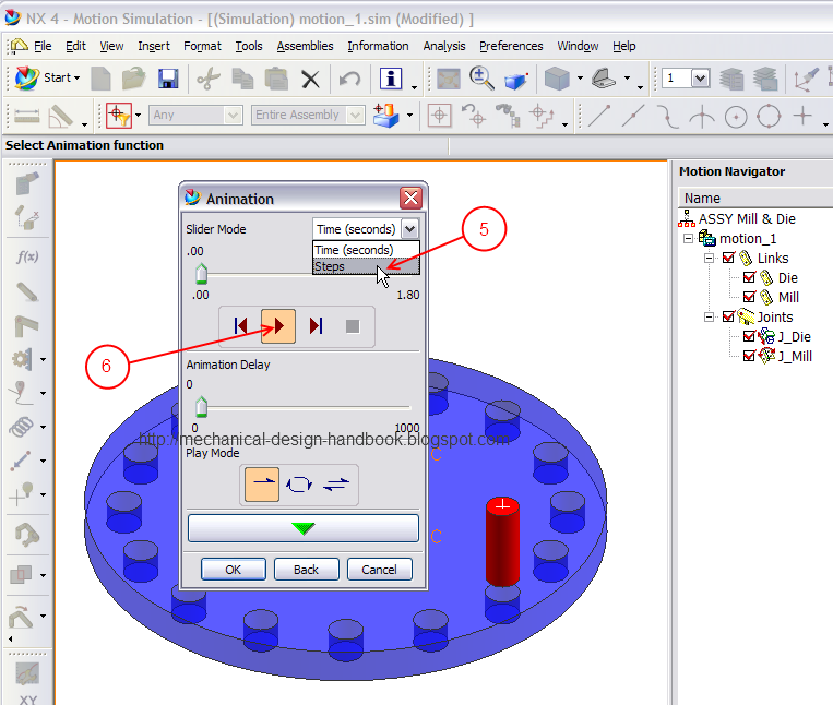
1. Select "Animation" command
2. Enter the time for simulation in seconds e.g. 1.8 seconds mean the cycle time of machine speed of 2,000 pcs/h.
3. Enter number steps for simulation. The more steps, the smoother simulation results. Here I put 360 steps, which is easy to trace for every 1 degree in timing diagram.
4. Click Ok to confirm.

5. Change the domain to steps instead of time, just for easier tracing purpose.
6. Click "Play" button to see the simulation.

We can find the interference between the indexing mill and punch die during the motion simulation using UG NX4 motion simulation module. This is because the functions set for both drivers are not as per the timing diagram designed previously.
Next post will show how to use "graphing" and "spreadsheet run" to set the UG NX4 motion simulation as per the timing diagram. And you can watch for the result of effort to optimize the timing diagram in 3D Motion.
Further reading:

Movement of the punch die is different from the indexing mill. It moves only in linear motion along Z axis (normal to top face of indexing mill). The joint for this kind of movement is called "Slider" joint. Here is how to set it:
1. Select Joint command.
2. Select "Slider" joint icon in the joint dialog box.
3. Select first link icon.
4. Select link "Die" as we previously created

5. Click at the "Orientation on the first link" icon.
6. Select "Point" from the drop-down menu.
7. Select center point of the cylinder as shown above to define the location of the slider joint.

8. Select "Vector" from the drop-down menu to define the direction of the slider joint.
9. Select the bottom face of cylinder to define the vector perpendicular to that plane. See the Z axis pointing downward.
10. Rename the slider joint to "J_Die".
11. Click Ok to confirm.
The slider joint setting procedures are almost done. Still to set the driver of this joint.
1. Right-click at the slider joint J_Die and select Edit to open the dialog box.
2. Change the slider joint motion driver to "Constant".
3. Type any value in the velocity text box e.g. 50. This sets the velocity of this slider joint to 50 mm/s.
4. Click Ok to confirm.
We've finished the setting procedures for motion simulation and we can now start simulation. But please note that the movement of indexing mill and punch are still not the same as what we need.

To see the motion simulation, follows the steps below:
1. Select "Animation" command
2. Enter the time for simulation in seconds e.g. 1.8 seconds mean the cycle time of machine speed of 2,000 pcs/h.
3. Enter number steps for simulation. The more steps, the smoother simulation results. Here I put 360 steps, which is easy to trace for every 1 degree in timing diagram.
4. Click Ok to confirm.
5. Change the domain to steps instead of time, just for easier tracing purpose.
6. Click "Play" button to see the simulation.

We can find the interference between the indexing mill and punch die during the motion simulation using UG NX4 motion simulation module. This is because the functions set for both drivers are not as per the timing diagram designed previously.
Next post will show how to use "graphing" and "spreadsheet run" to set the UG NX4 motion simulation as per the timing diagram. And you can watch for the result of effort to optimize the timing diagram in 3D Motion.
Further reading:
- Working Model: Motion Simulation for Engineering, Animation, and Prototyping - Complete Software Boxed Package (For Macintosh, Includes 3 Floppy Disks) (Knowledge Revolution)
- Motion Simulation and Mechanism Design with SolidWorks Motion 2009
- Motion Simulation and Mechanism Design with COSMOSMotion 2007


Comments