How to use Unigraphics NX4 Motion Simulation in Timing Diagram Design Process - Part 2
Let's continue from previous post. Now it's time to see our previous calculation for the timing diagram of indexing mill and punch die in 3D Motion Simulation using Unigraphics (UG) NX4. Though we have made motion simulation in excel spreadsheet using excel VBA, it's much better and easier to do it in UG motion. The UG NX4 Assembly model is prepared as shown below.
 Mating conditions of the assembly model is as according to the sketch shown in [Timing Diagram (Part 1 - No Overlap Movement)].
New to UG NX4 Motion Simulation? No problem, just follow our guideline in step-by-step, and you will find it easy to use. Let's see how to do...
We can enter into Motion Simulation Environment as shown below.
 In motion simulation environment, we see all commands are disabled. Then we have to right-click on the assembly file and select New Simulation.
 This command will create necessary UG files and put them into new folder automatically (see new folder and files in windows explorer).
 Click at the environment command (calculator icon) and select "Kinematics". This is because we are going to use "Spreadsheet Run" to control the motion.

Then we define the links to use in motion simulation by just following the steps shown in the pictures.
1. Click link command.
2. Select object, for this case select the indexing mill.
3. Enter name of the link, for this case enter Mill.
4. Click Ok to confirm.
 Do the same for the punch die. Now we have 2 links to use in motion simulation. But we can't start simulation yet. We still need to define the joint for each link and we have to make the "degrees of freedom" become zero, otherwise we need to simulate using "Dynamics" environment.
Let's starting defining joint of indexing mill. There are a lot of types to define, but for this indexing mill we select "revolute joint". The revolute joint has 1 degree of freedom because it can only rotate in Z-direction and this is what we want for the indexing mill. To set the joint, just follow the following steps:
1. Select Joint command.
2. Select "Revolute joint" icon (default) then select the "link". For this case, select the Mill.
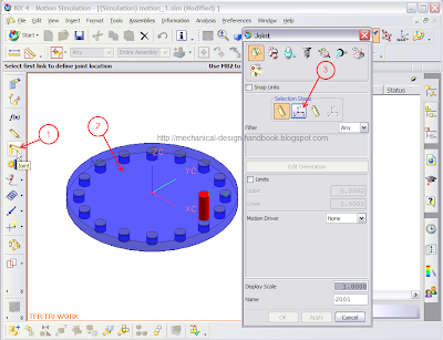 The revolute joint definition is not complete yet because we have to define the point and direction of the joint. After selection of the link in step 2, the Joint windows automatically switch command to define the orientation of joint on the first link.
3. If not yet selected, select "Orientation of joint on the first link".
 4. Select "Vector".
5. Select the top face of the indexing mill.
These steps are to define the direction of the joint. For the revolute joint, we need to define the Z-direction for rotation axis. By selecting the top face of the mill, we define the vector normal to that plane.
 Now the revolute joint direction is defined, but we still have to define the exact location (point) of the rotation axis, for this case, it's the center of the indexing mill.
6. Change from "Vector" to "Point".
7. Select the center point of the index mill.
8. Rename the joint to "J_Mill". This is for reference and easy to trace back.
9. Click Ok to confirm.
It's still not finished yet for the setting of the revolute joint for indexing mill. Though, the vector and point are fully defined, but there's nothing define how it moves yet. At each instance, the revolute joint can rotate to any degrees. Therefore we need to define the last thing for this revolute joint, Motion Driver.
 We can set the Motion Driver as follows:
1. Select "Constant"
2. Enter numerical value at "Velocity" box e.g. 100
3. Click Ok to confirm.
The above process sets the motion driver to have constant velocity of 100 deg/s. You may argue that the motion of this indexing mill as per the previous posts must be "cycloid" not constant velocity. Yes, that's right. But that is for later. For the moment it's enough to define it like this.
Let's take a break for a moment and continue in the next post.

New to UG NX4 Motion Simulation? No problem, just follow our guideline in step-by-step, and you will find it easy to use. Let's see how to do...
We can enter into Motion Simulation Environment as shown below.


Then we define the links to use in motion simulation by just following the steps shown in the pictures.
1. Click link command.
2. Select object, for this case select the indexing mill.
3. Enter name of the link, for this case enter Mill.
4. Click Ok to confirm.

Let's starting defining joint of indexing mill. There are a lot of types to define, but for this indexing mill we select "revolute joint". The revolute joint has 1 degree of freedom because it can only rotate in Z-direction and this is what we want for the indexing mill. To set the joint, just follow the following steps:
1. Select Joint command.
2. Select "Revolute joint" icon (default) then select the "link". For this case, select the Mill.

3. If not yet selected, select "Orientation of joint on the first link".

5. Select the top face of the indexing mill.
These steps are to define the direction of the joint. For the revolute joint, we need to define the Z-direction for rotation axis. By selecting the top face of the mill, we define the vector normal to that plane.

6. Change from "Vector" to "Point".
7. Select the center point of the index mill.
8. Rename the joint to "J_Mill". This is for reference and easy to trace back.
9. Click Ok to confirm.
It's still not finished yet for the setting of the revolute joint for indexing mill. Though, the vector and point are fully defined, but there's nothing define how it moves yet. At each instance, the revolute joint can rotate to any degrees. Therefore we need to define the last thing for this revolute joint, Motion Driver.

1. Select "Constant"
2. Enter numerical value at "Velocity" box e.g. 100
3. Click Ok to confirm.
The above process sets the motion driver to have constant velocity of 100 deg/s. You may argue that the motion of this indexing mill as per the previous posts must be "cycloid" not constant velocity. Yes, that's right. But that is for later. For the moment it's enough to define it like this.
Let's take a break for a moment and continue in the next post.


Comments