Timing Diagram (Part 1 - No Overlap Movement)
When I search in Google for "timing diagram", I found a lot of results about electrical timing diagram software but they're not about what I'm going to tell. Timing Diagram in my meaning is a tool that represents the sequences of movement of mechanisms. It is a very useful diagram for mechanical design engineers to understand how each part of the machine works together.
From the timing diagram, we can find the opportunity to reduce the acceleration (force) of the moving parts so as to reduce the wear in machine.
Experience shows that a lot of mechanisms have been designed without using "overlap" movement. This makes the machine parts move from one point to another point in short period. But if we provide the overlap motion between relevant mechanisms, the machine parts can travel between the same distance, but in longer period. This reduces the acceleration of the parts, that means lower forces exerted on the parts and result in less wear on the parts.
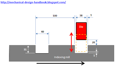
Let's have a look at the example of simple machine that press the die into the hole of the indexing mill.
Operation overview:
The indexing mill has 24 stops and it moves 100 mm during each index. It uses the indexing cam with Cycloid Cam Profile having indexing angle of 150 degrees. After the mill stops, the die then moves down using Cycloid cam profile until it reaches the bottom of the holes with 1 mm gap (traveling distance = 20+31-1 = 50 mm). And the die has to stay at the bottom for 100 degrees, then it moves up before the indexing mill rotate again in the next cycle.
If we make a timing diagram without any overlap, we will come up as follows.

With no overlap movement, the die has to wait until the indexing mill (turret) has finished indexing then it will move down to the bottom of the mill and stay there for 100 degrees. After that, it moves up. Then the indexing mill start indexing again in the next cycle.
The remaining angle for the die movement can be calculated using the following equation:
Cam Angle for die movement = 360 - mill indexing angle - angle for die at the bottom
So, cam angle for die movement = 360 - 150 - 100 = 110 degrees
We have to split the die movement for up and down equally. Hence, the cam angle for die movement up or down = 110/2 = 55 degrees.
The timing diagram is then constructed by using 150 degrees in the timing diagram as a starting point of die moving down. So the die fully moves down at 150+55 = 205 degrees. Then it has to stay at the bottom for 100 degrees, that means the die starts moving up again at 205+100 = 305 degrees. The die finishes move up at 305+55 = 360 degrees. Then the next cycle starts again.
Let's calculate the maximum acceleration of die when moving up and down in the next post [Timing Diagram (Part 2 - Maximum acceleration calculation)]. Later we can compare this result with the acceleration after making some overlap movement between indexing mill and die. At the end we will write a simple Microsoft Excel program to simulate the motion of indexing mill and die for both cases at the same time.
" By properly design the timing diagram, we can make machine moves smoother even at higher speed. "We often draw the timing diagram using cam angle (in degree) in horizontal axis and use the movement of mechanism (in mm) in vertical axis.
From the timing diagram, we can find the opportunity to reduce the acceleration (force) of the moving parts so as to reduce the wear in machine.
Experience shows that a lot of mechanisms have been designed without using "overlap" movement. This makes the machine parts move from one point to another point in short period. But if we provide the overlap motion between relevant mechanisms, the machine parts can travel between the same distance, but in longer period. This reduces the acceleration of the parts, that means lower forces exerted on the parts and result in less wear on the parts.
Let's have a look at the example of simple machine that press the die into the hole of the indexing mill.

The indexing mill has 24 stops and it moves 100 mm during each index. It uses the indexing cam with Cycloid Cam Profile having indexing angle of 150 degrees. After the mill stops, the die then moves down using Cycloid cam profile until it reaches the bottom of the holes with 1 mm gap (traveling distance = 20+31-1 = 50 mm). And the die has to stay at the bottom for 100 degrees, then it moves up before the indexing mill rotate again in the next cycle.
If we make a timing diagram without any overlap, we will come up as follows.

The remaining angle for the die movement can be calculated using the following equation:
Cam Angle for die movement = 360 - mill indexing angle - angle for die at the bottom
So, cam angle for die movement = 360 - 150 - 100 = 110 degrees
We have to split the die movement for up and down equally. Hence, the cam angle for die movement up or down = 110/2 = 55 degrees.
The timing diagram is then constructed by using 150 degrees in the timing diagram as a starting point of die moving down. So the die fully moves down at 150+55 = 205 degrees. Then it has to stay at the bottom for 100 degrees, that means the die starts moving up again at 205+100 = 305 degrees. The die finishes move up at 305+55 = 360 degrees. Then the next cycle starts again.
This seems very easy to calculate. But is it good enough?
Let's calculate the maximum acceleration of die when moving up and down in the next post [Timing Diagram (Part 2 - Maximum acceleration calculation)]. Later we can compare this result with the acceleration after making some overlap movement between indexing mill and die. At the end we will write a simple Microsoft Excel program to simulate the motion of indexing mill and die for both cases at the same time.


Comments